RotaryCell / build guide
Complete wiring overview
Use this diagram as the connection map for the finished RotaryCell assembly. It shows how the LilyGO controller, Audio/Reset A4 board, AG1171 carrier, charging connector and telephone network connect before everything is fitted into the phone.
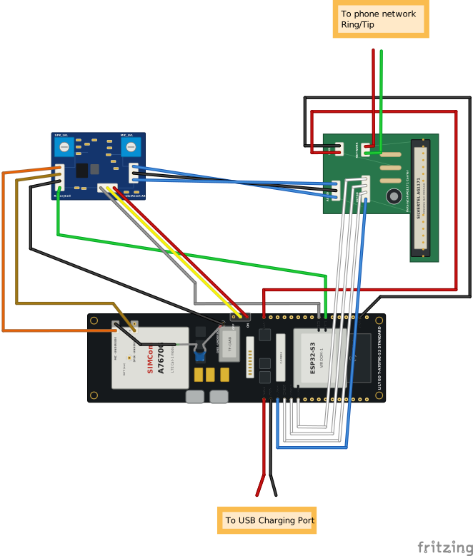
Ring and Tip connections vary by telephone
The diagram shows the AG1171 RING and TIP outputs going to the telephone
network, but it cannot show universal network-block terminals. Network
blocks, terminal markings and factory wiring differ among telephone models
and revisions. Use the schematic inside your telephone or trace the two
points formerly connected to its incoming line cord. Do not choose
terminals by wire color or by copying a photograph of a different phone.
The converted telephone must also remain disconnected from any active
outside telephone line.
The line colors make the individual paths easier to follow in the drawing.
They do not specify the colors your finished harness must use. Identify and
verify every conductor by its labeled endpoints, especially the four audio
connections: GPIO36 audio signal, GND, SPEK+ and MIC+.
The drawing is an electrical overview rather than a physical routing plan. Later installation photographs show how to dress the wires around the dial, bells, hookswitch and the particular network block in your telephone.