RotaryCell / build guide
Fit the rear charging connector
Western Electric 500-series phones commonly have one of two rear openings. The rear connector is still an area I am refining, but these are the two current designs I prefer for the corresponding phone types. They are already a considerable improvement over hot glue and dreams.
| Original connection | Printed insert |
|---|---|
| Permanently attached or captive line cord through an arched opening | Arch_USB_TestFit_R1.stl |
| Removable line cord using the rectangular modular-jack opening | Rect_USB_TestFit_R3.stl |
Both parts were printed in PLA at 100% scale with 0.2 mm layers and three walls. Start with the outside face on the build plate as supplied. Both models need supports, but the best support placement and settings depend heavily on the printer and slicer.
These are small, detail-sensitive parts with a narrow socket opening and thin retention features. They require a well-tuned printer to come out cleanly. A resin printer may be especially well suited to them. Whichever process you use, remove the supports carefully, clean up any support scars or first-layer bulge, and test-fit the empty insert before installing the breakout board.
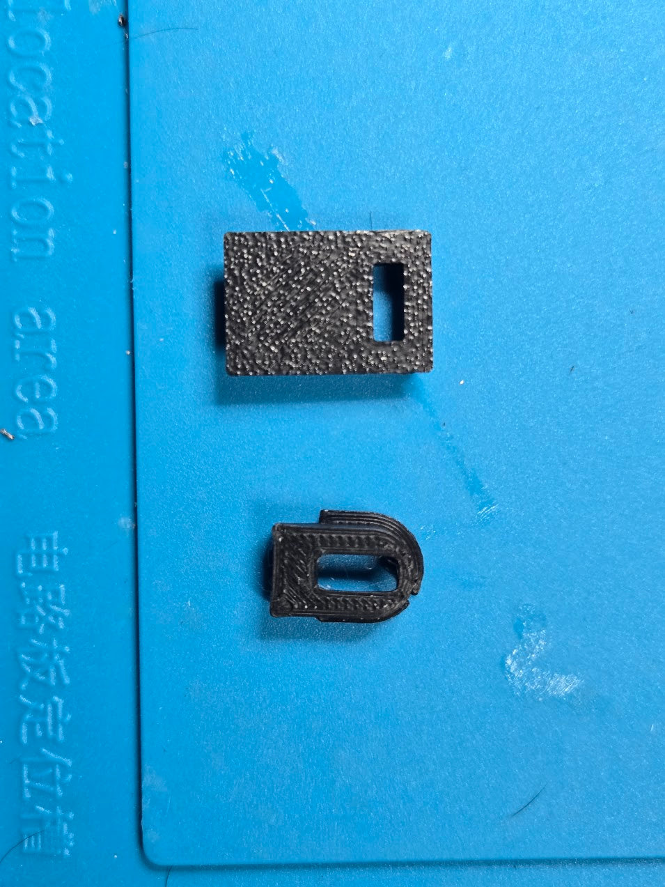
Captive-cord phone: Arch R1
The arched insert follows the original cord opening and uses a small inside shoulder to keep it from being pushed outward. The original metal tab clears the lower portion of the insert.
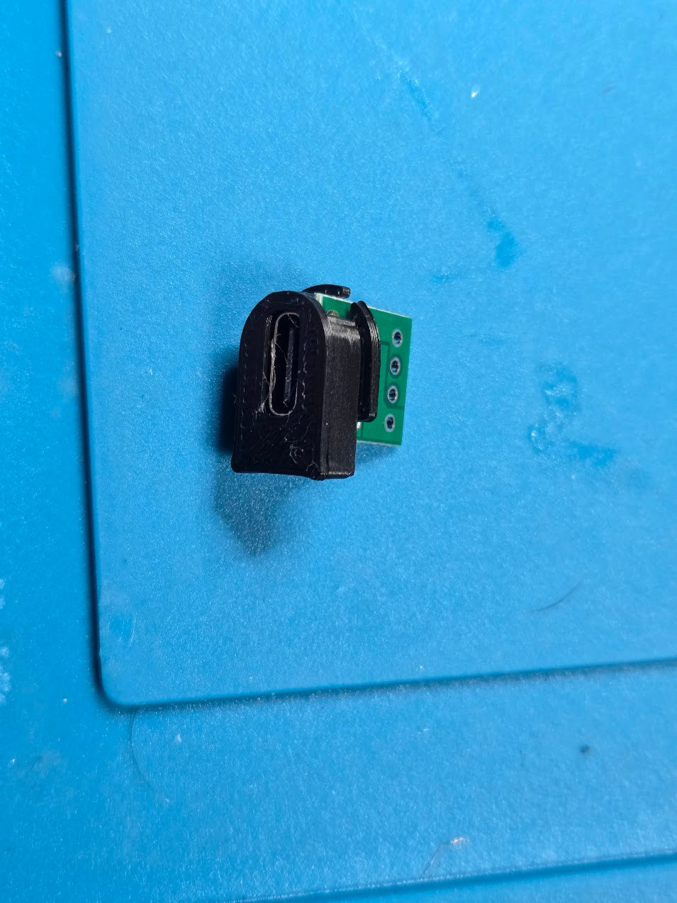
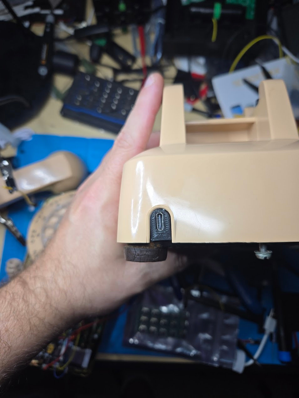
Modular-jack phone: Rect R3
The rectangular insert slides into the original modular-jack slot. Its exterior lip covers the open lower portion of the cutout, while the extended body engages the metal retaining tab inside the telephone. R3 is the current revision, but I am still refining its retention and fit.
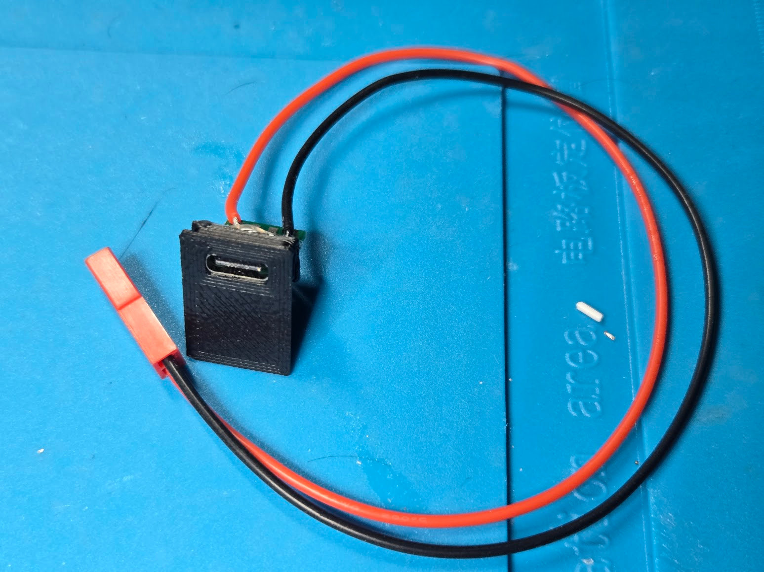
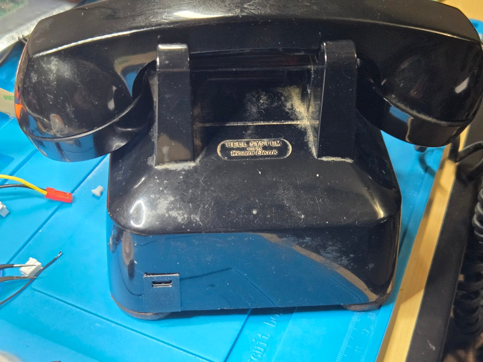
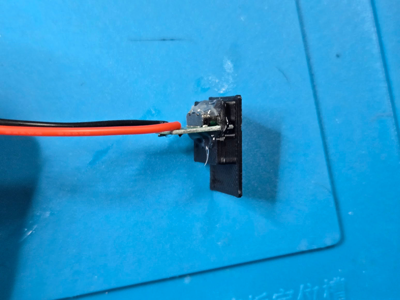
I used these 20-piece USB-C female breakout boards. They press into the printed channel from behind with some effort. Push the board in evenly, with its socket facing the outside of the phone, and avoid loading the USB-C receptacle itself.
Solder only the breakout's V+ (VBUS) and GND pads to the charging harness prepared earlier. The USB data pads remain unconnected. These boards do not include the USB-C configuration resistors needed to request power from a USB-C source, so power the phone with a USB-A-to-USB-C cable. A USB-C-to-USB-C cable may provide no power at all.
The press fit locates the connector. I secured the back of the breakout with hot glue for retention and strain relief—plus dreams, as previously mentioned. Keep the glue clear of the USB-C socket and the surfaces that fit against the phone. After installation, verify that the plug seats fully and cannot push the insert into the telephone.
Old telephone shells and printed dimensions vary slightly. Remove print-edge bulge before enlarging an opening; if adjustment is necessary, a light pass with a file is usually enough.