RotaryCell / build guide
Remove the battery holder
The factory 18650 holder occupies the space needed by the finished RotaryCell assembly. Its large solder joints conduct heat into the holder and board, so a small USB-C iron is poorly suited to this step. I use a Hakko FX-888-series iron with a broad tip, fresh solder, flux and desoldering braid.
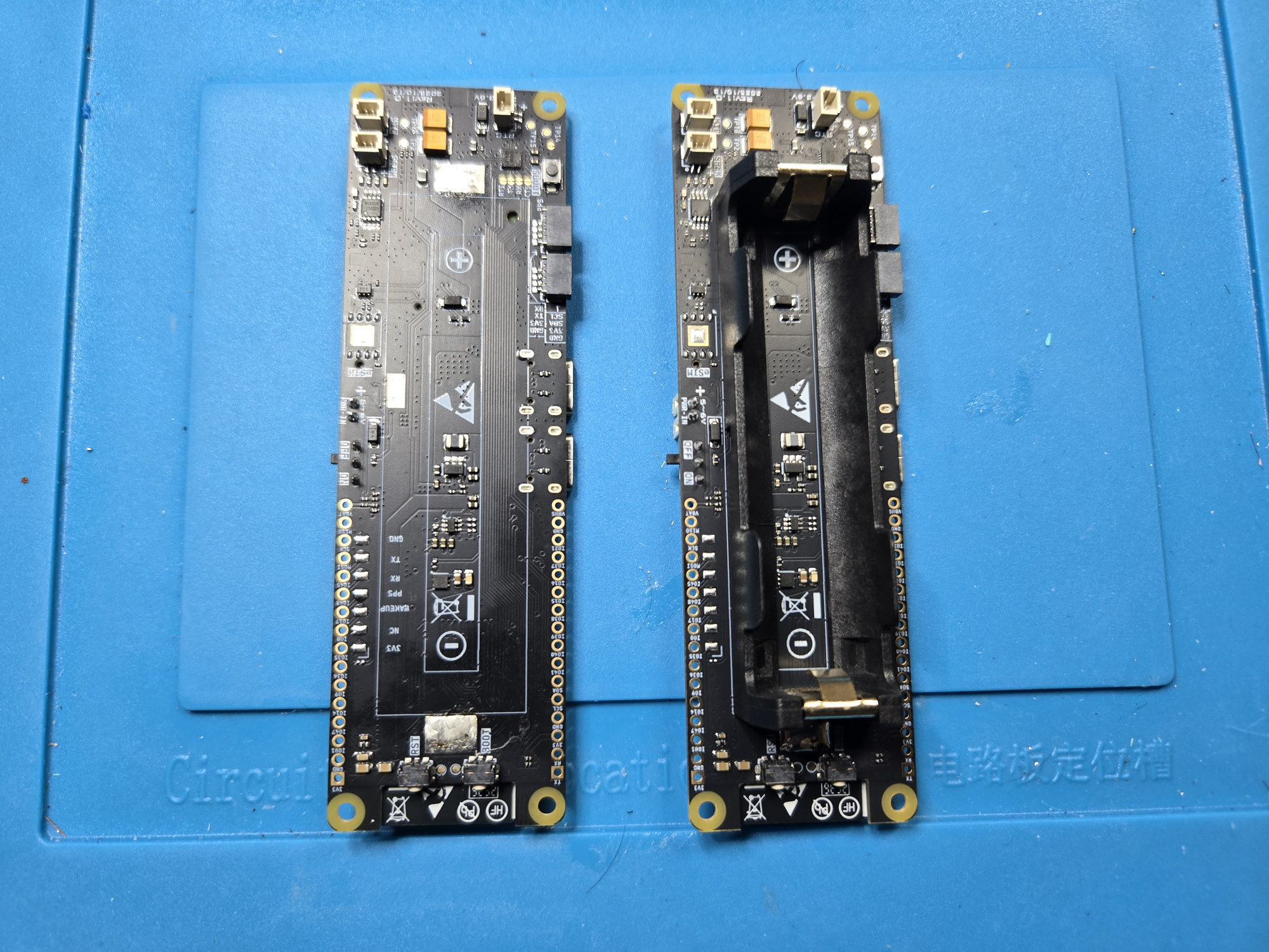
1. Support the board
Place the LilyGO on a stable, heat-resistant surface without loading the modem, USB connectors or small surface-mount parts. Note the holder orientation and photograph both battery joints before applying heat.
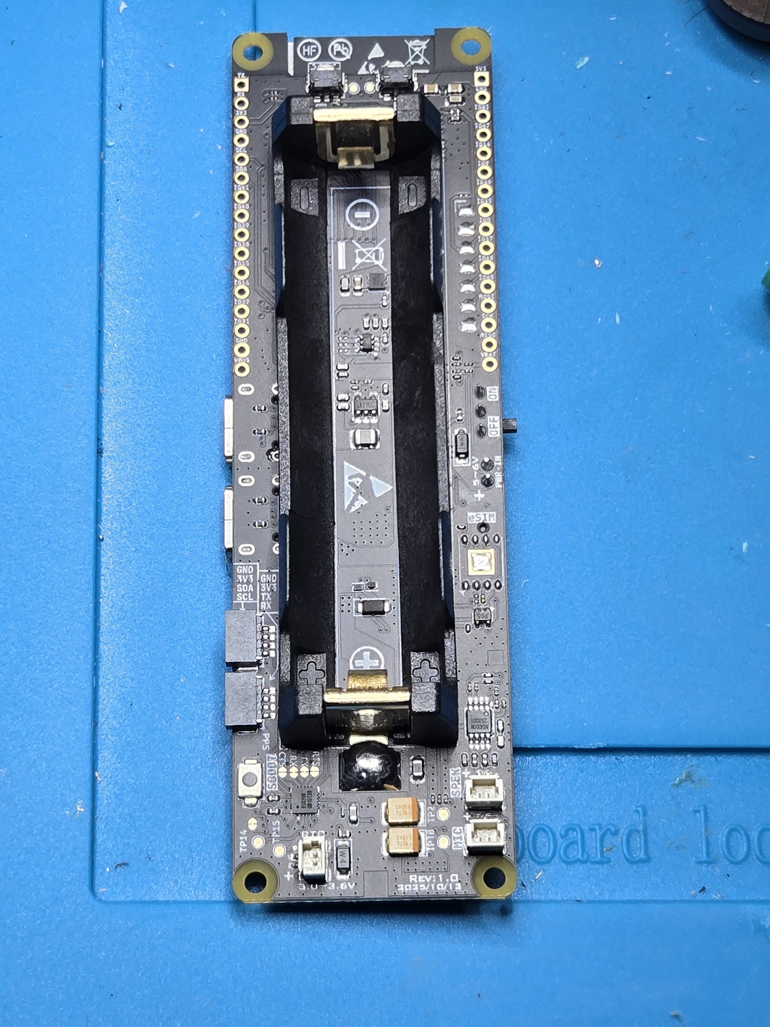
The holder is retained by the large joints at its two ends. The photograph also records the original polarity and holder orientation before any heat is applied.
2. Clear the joints
Add flux and a small amount of fresh solder to improve heat transfer. Heat each joint with the broad tip and remove solder with braid. Work a little at a time rather than pulling against a joint that is still solid.
3. Lift the holder away
Remove the holder only when its attachment points move freely. Do not pry against the PCB or use the copper pads as levers.
4. Clean and inspect
Remove remaining solder and flux as needed. Confirm that both battery pads are flat, attached to the board and free of bridges or torn copper.
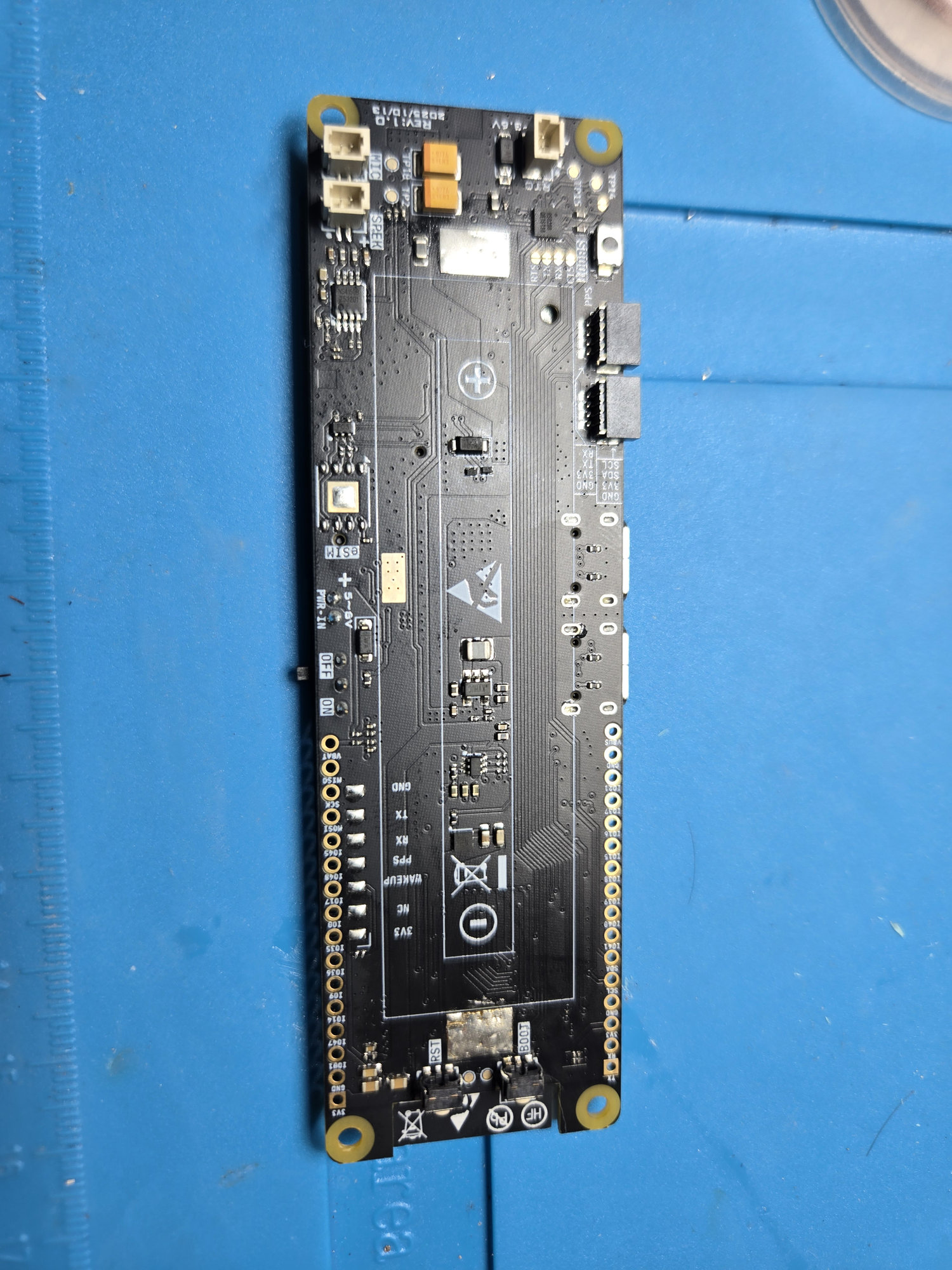
With the holder removed, inspect both former attachment areas and the exposed board surface. The pads should remain attached and no neighboring components should have moved.
Stop here if either pad lifted, a nearby component moved, or the board shows heat damage. Repair and verify the battery path before adding wires.