RotaryCell / build guide
Prepare the cables
This page records the cable lengths, colors and pin assignments used in the working build. It assumes you already know how to strip wire and crimp the contacts correctly.
Wire colors are not part of the circuit
You do not need to copy my wire colors or follow the same overall color scheme. I used a combination of what I had available and what helped me keep the wiring straight. Use colors that let you distinguish conductors wherever polarity, connector orientation or signal identity matters, and record any substitutions you make.
Audio board to carrier
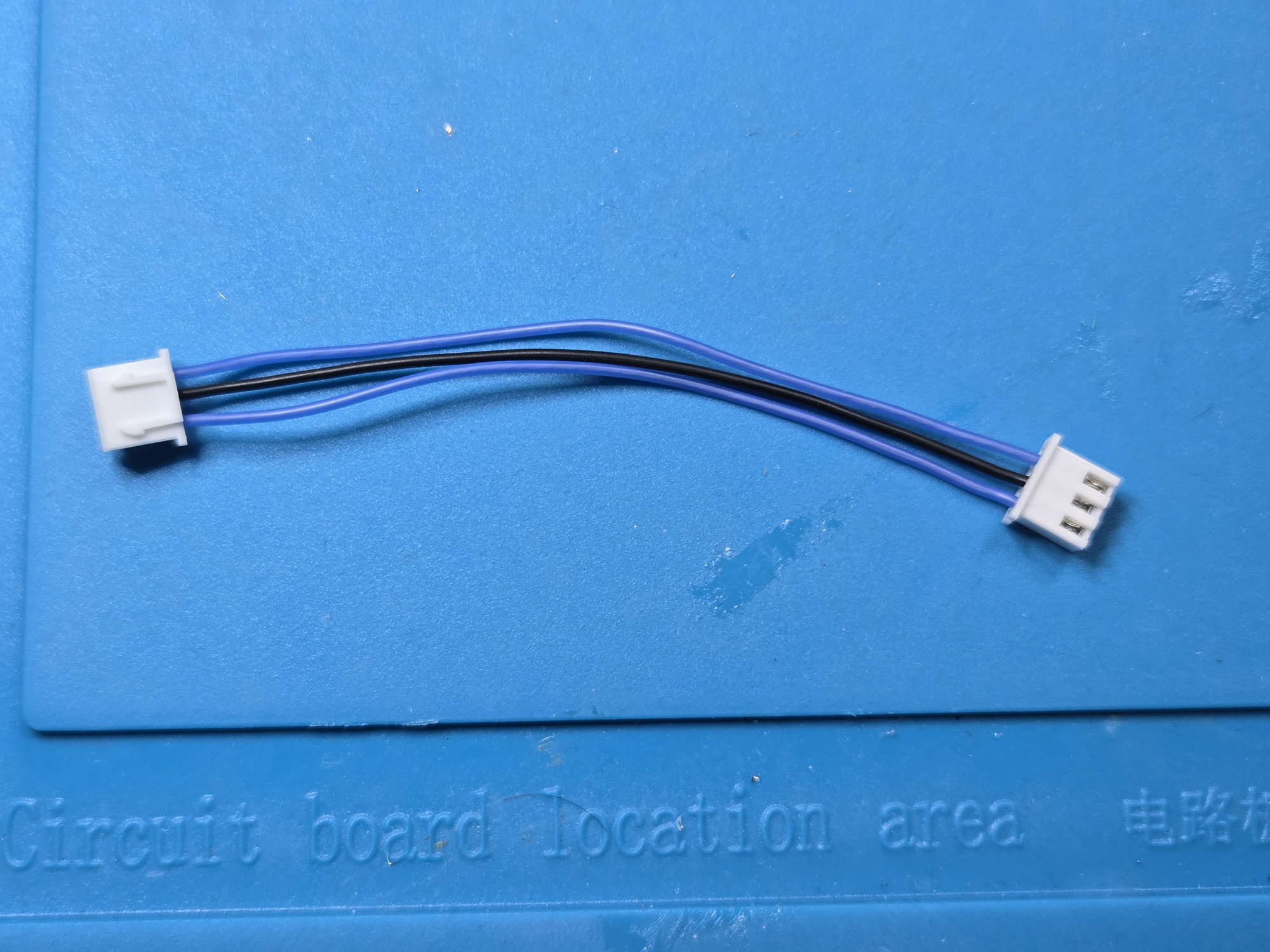
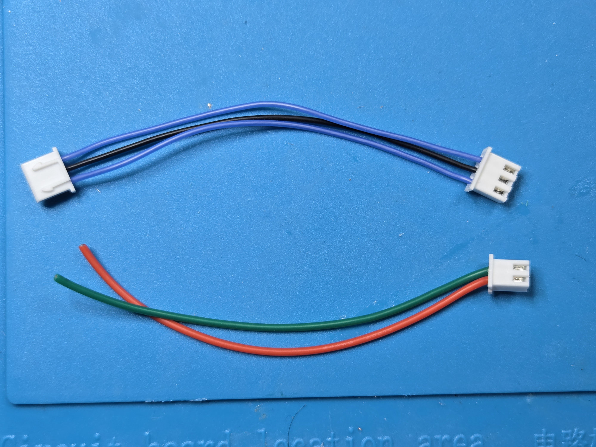
Use a 10 cm three-conductor cable between Audio A4 J2 and carrier U2. It is wired straight through, with blue outer conductors and black in the center.
| Audio A4 J2 | Carrier U2 | Signal |
|---|---|---|
| Pin 1 | Pin 1 | VIN |
| Pin 2 | Pin 2 | GND |
| Pin 3 | Pin 3 | VOUT |
Carrier to telephone network
The two-position NETWORK connector on the carrier runs to the telephone's
network block. Use green for tip and red for ring so the original
telephone convention remains obvious during installation. Leave the network
block ends untrimmed until the boards are in the phone.
Remaining harnesses
I use this crimp tool and connector kit for the harnesses. The kit also supplies the through-hole headers for the boards.
The four charging, battery, AG1171 power and AG1171 signal harnesses use 10 cm
conductors. Current-carrying red, yellow and black conductors are 24 AWG, while
signal-only conductors are 28 AWG. The three-wire hardware-reset harness uses
16 cm red and yellow 24 AWG conductors and an 18 cm green 28 AWG trigger wire.
The LilyGO audio harness uses 28 AWG wire: 14 cm black common, 18 cm blue tone,
and 10 cm red SPEK+ and MIC+ leads. Both two-position audio cables begin at
10 cm; remove the black SPEK- conductor and trim the black MIC- conductor
during final soldering.
Check the finished cable
Verify every conductor end-to-end and check for unintended connections between adjacent pins. Gently check that each contact is retained by its housing.
Connector names repeat
Audio A4 U2 is the reset connector. Carrier U2 is the audio connector. Always include the board name when checking a connection.