RotaryCell / build guide
Inspect the prepared controller
Inspect and test the LilyGO before plugging in the Audio/Reset board, AG1171 carrier or battery.
Visual inspection
- Battery-positive and
BATNleads are identified and insulated. VBATand system GND are routed to the carrier power connector.SPEK-is insulated and remains floating.- The
MIC-reference capacitor is present and insulated. - GPIO15, GPIO16, GPIO21, GPIO35, GPIO36 and GPIO37 match their labeled harness positions.
- The power-switch taps have strain relief and cannot touch neighboring pads.
- Both USB ports and both QWIIC connectors remain accessible.
Meter checks
With no battery or USB cable connected:
- Check for an unintended short between battery positive and
BATN. - Verify continuity through each new lead from its LilyGO pad to the correct connector contact.
- Confirm that system GND and the carrier ground lead are continuous.
- Confirm that the carrier ground lead is not wired directly to the raw
holder-negative/
BATNconnection. - Verify that adjacent GPIO and audio contacts are not bridged.
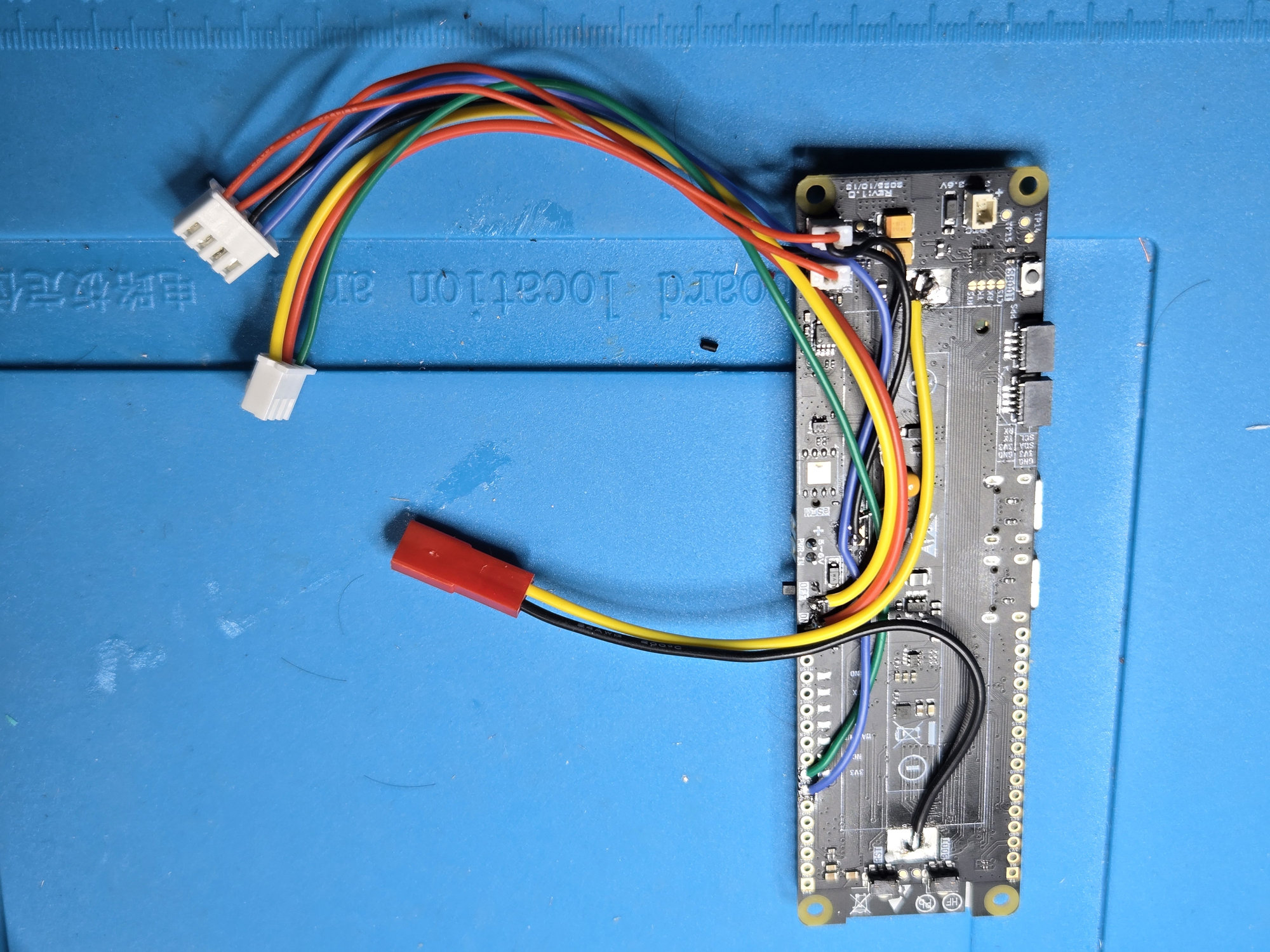
Use this overview to compare the general wire routing before fitting the carrier. Exact solder joints are shown on the connection page; use the numbered meter checks above to verify the electrical connections rather than judging continuity from a photograph.
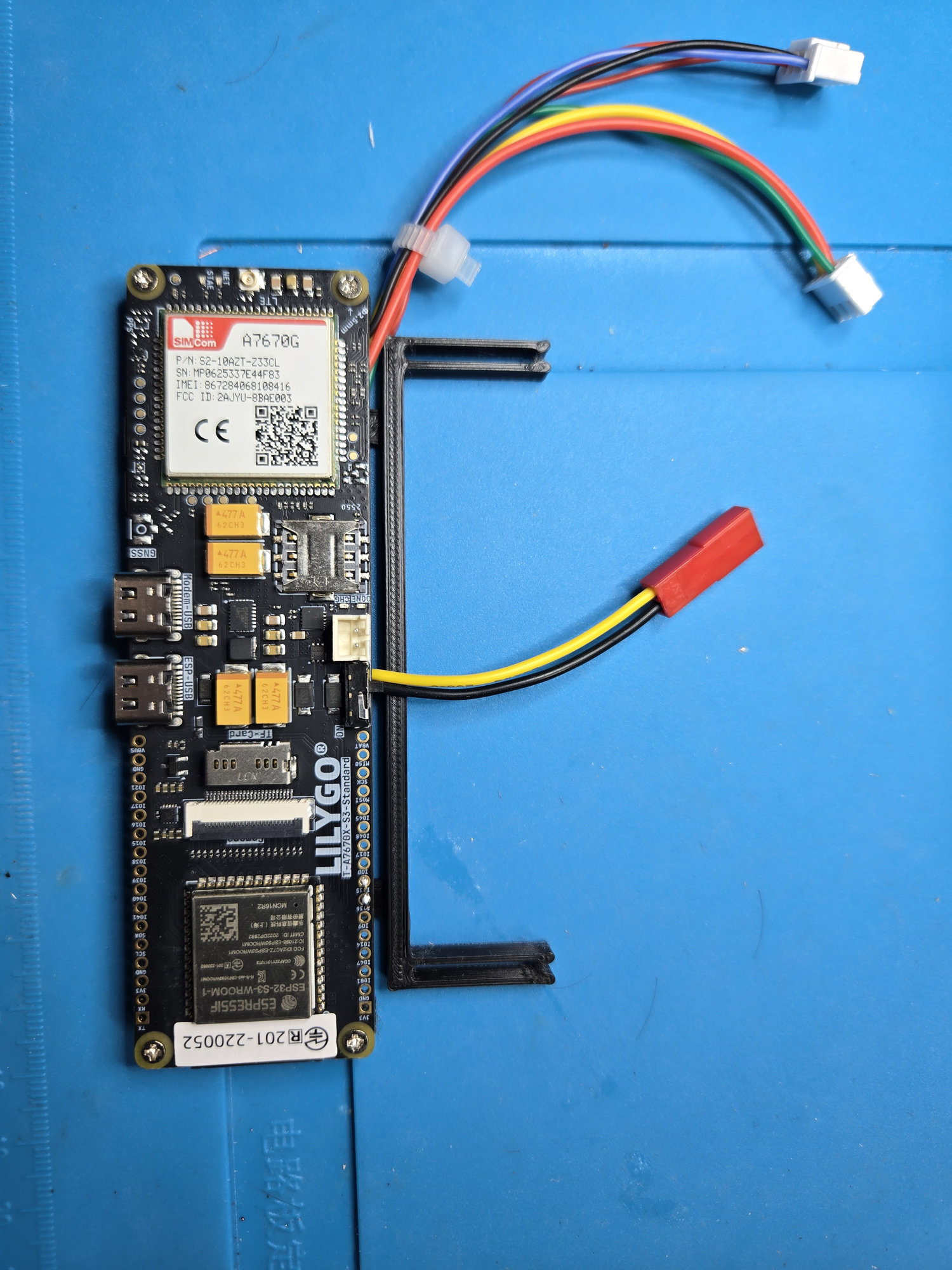
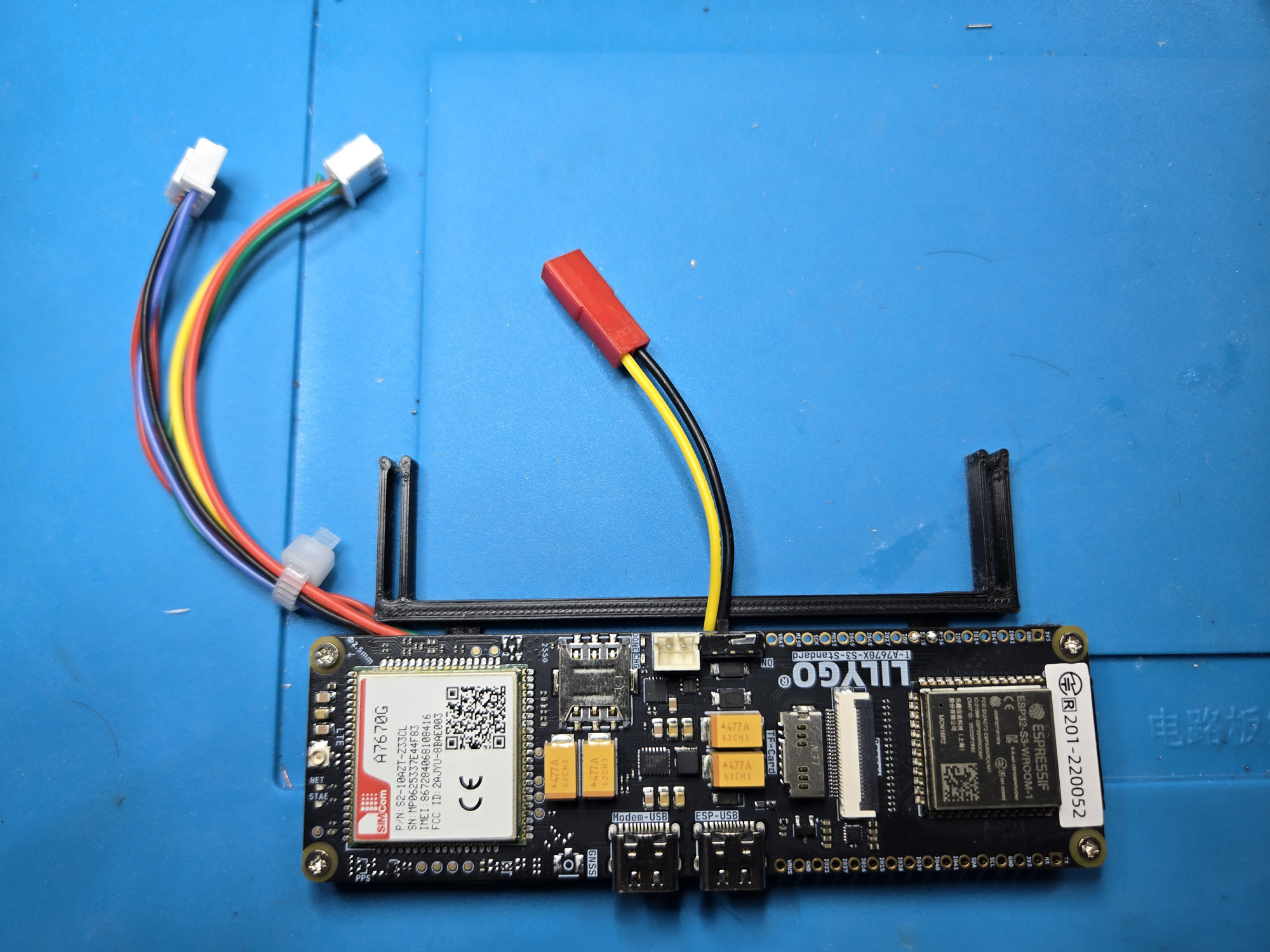
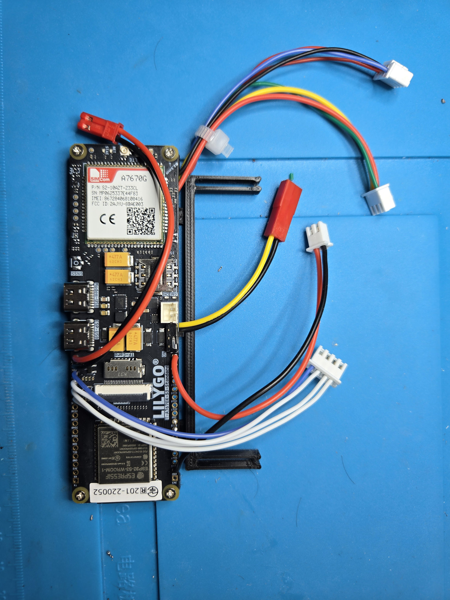
The front views confirm that the prepared controller seats fully in the carrier and that the battery, signal and reset connectors remain outside its edges.
After the unpowered checks pass, power the LilyGO by USB without the other boards attached and confirm that it starts normally. Battery, charging and A4 reset tests belong in the staged commissioning procedure after their respective connections have been verified.
The LilyGO starts from USB, every added conductor matches its documented node, and no unpowered short is present. Continue to custom-board assembly.