RotaryCell / build guide
Print the mounting parts
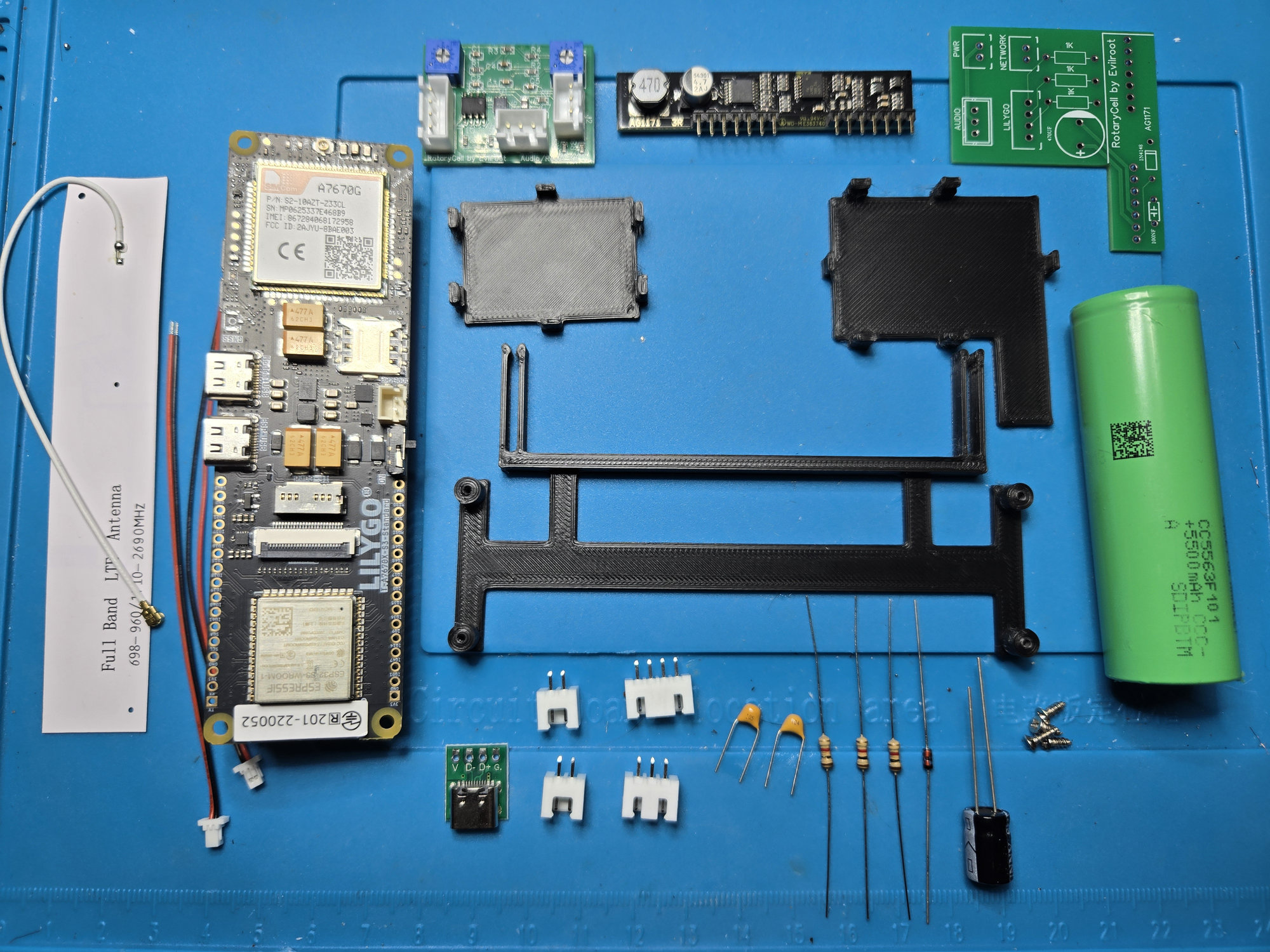
The build shown in this guide uses three printed mounting parts. They are simple functional prints; there is no need for unusually fine layers or cosmetic finishing.
| Part | File | Purpose |
|---|---|---|
| LilyGO dial-support carrier | Download STL | Screws to the LilyGO and clips over the two metal dial supports |
| Audio/Reset A4 carrier | Download STL | Holds the small audio board and attaches to the telephone base with VHB tape |
| AG1171 carrier | Download STL | Holds the AG1171 carrier board and attaches to the telephone base with VHB tape |
Print settings
I printed the parts in PLA at 100% scale with 0.2 mm layers. Three walls are sufficient. PLA also avoids the stringing that PETG can produce around the clips, bosses and other narrow features. Print each part flat in the orientation supplied by the STL; the three interior carriers do not require supports.
The two small carriers print with their broad, flat tape faces on the build plate. The LilyGO carrier also prints flat, with its four screw bosses and the two dial-support clips extending upward.
Hardware and installation
The LilyGO attaches with four M2 plastic-tapping screws. Its pilot holes are blind, so use short screws and stop when the board is secure. The finished carrier clips onto the two metal posts that support the telephone dial; it does not need adhesive.
Apply 3M VHB tape to the flat underside of the two small carriers. Their final locations are shown later on the installation page.
The rear USB-C holder is a separate, phone-specific part. The guide includes tested inserts for both the captive-cord arch and the rectangular modular-jack opening. Print the appropriate model after choosing the rear connector arrangement that fits your telephone.